How to Draw a Tunnel in Plan View
What is Section Drawing?
Section drawing can exist explained with a simple analogy: slicing a loaf of bread.
If you had an unsliced loaf of fruit and nut bread and wanted to know how fruity and nutty information technology was, you would slice the loaf across the middle (say) and look at the sliced faceof 1 of the two halves.
In an exactly similar manner, if on a figurer y'all had a drawing of a three-dimensional object, say of an AA battery or a shopping mall, and you wanted to know what the inside looked at a particular betoken along its length (as a simple case), a 'section drawing' would display details of the ane of the faces created by the slicing.
Cutting Planes
To make up one's mind where exactly you desire to slice a three-dimensional computer object, CAD (Computer-Aided-Design) programs crave yous to position a aeroplane (ie a apartment surface) through the object to show where you intend slicing the object.
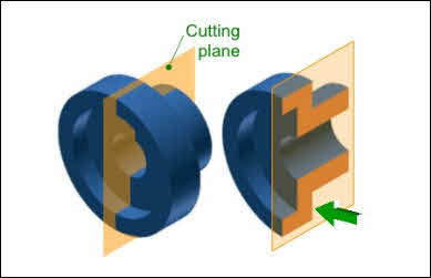
The concept of cutting planes
Exist aware that a cutting plane does not have to be a single flat surface... information technology tin as well be a multi-segment assembly of several planes. This kind of cutting plane effectively combines multiple section drawings into one.
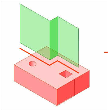
A multi-segment cut plane
The Purpose of a Section Cartoon
Section Cartoon in Engineering science
Engineering objects often have complex inner structures, such as the inside of a jet engine. Like whatsoever mod-twenty-four hour period objects, they are manufactured based on drawings with comprehensive details.
It is frequently necessary for manufacturers to know what the inside of such objects looks similar. For example, they would need to know how the inner parts fit together for them to get together the overall object. A section drawing provides that information.
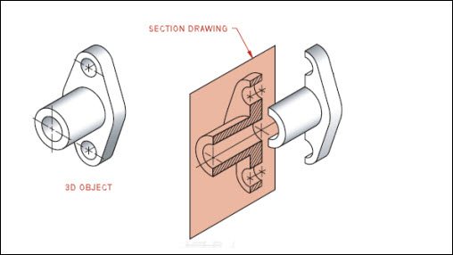
Caption of technology section drawing
Section Drawing in Compages
A building is a three-dimensional object. Architects depict buildings with drawings that include the thickness of flooring slabs, roof slabs, inner walls, outer walls, doors, windows, stairs, etc.
Architects oftentimes check the correctness of their design past examining a section drawing of the edifice. More chiefly, local planning departments always need a section drawing (or drawings) to decide whether to upshot a building allow for the structure of the building.
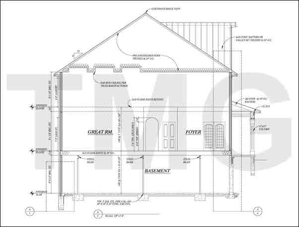
Architectural section drawing
What is a Wall Section?
Sometimes walls are non as simple equally a barrier of bricks or concrete blocks. Walls of single-family homes ofttimes have an interior wooden framework filled with insulating cloth (crossbar); industrial buildings often have a metallic framework with a waterproof bulwark sandwiched between two insulation layers.
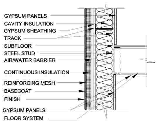
Wall Section Drawing Example
The Divergence Between Section and Elevation Drawings
A section drawing is a view taken after y'all 'piece' an object, so look at the surface created by the slicing.
An elevation drawing is a view taken from a point outside the object without whatsoever slicing.
In both cases, the object should exist standing on its base when the view is taken.
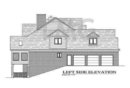
Elevation Drawing Case
Difference Betwixt Section and Detail Drawings
Every bit mentioned above, A section drawingis a view taken subsequently you 'piece' an object, and so look at thesurface created by the slicing.
A detail drawing magnifies a specific part of a larger cartoon. The specific office is oft too minor to be clearly seen in the larger drawing, hence the need for 'spot magnification.'
A detail cartoon is a view of a specific part of the complex drawing. It is oftentimes drawn on a separate sheet to provide space for the dimensions which could not be fitted into the complex drawing. Sometimes several item drawings will fit onto the separate sail.
The cartoon below contains two detail drawings in round outlines, magnifying parts of the larger drawing on the left.
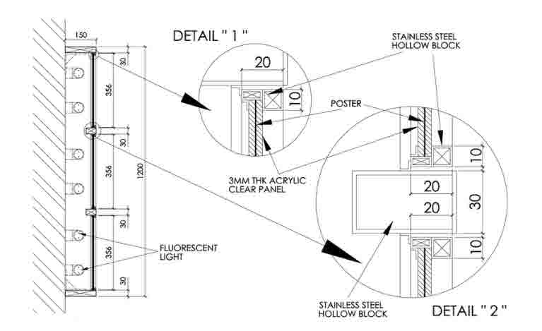
Many detail drawings contain section drawings as in the case above.
Types of Section Drawings
Total Department
A full section shows a slice across the unabridged object and is required when the object is not symmetrical.
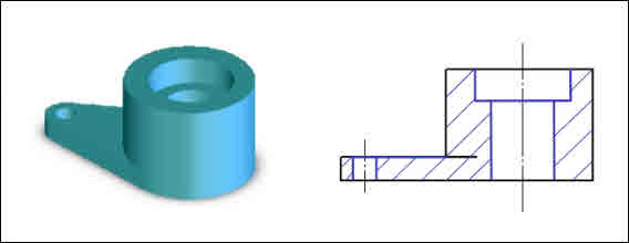
A total section cartoon
Half Department
When an object is symmetrical, it is frequently superfluous to describe the full section, since ane side of the section volition exist the mirror image of the other.
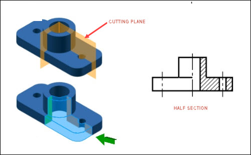
A half department drawing
Longitudinal Department
A longitudinal department drawing is when the cutting aeroplane is forth the larger axis of the object.
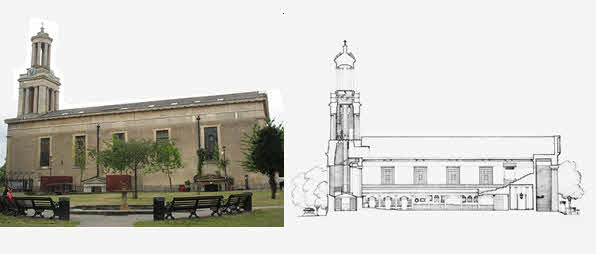
Above is a photograph of St Matthew's Church at Brixton, UK. A longitudinal department drawing of it is to its right.
Photo source: geograph.org.uk Drawing source: british-history.air-conditioning.uk
Lateral Department
A lateral section cartoon is more correctly termed atransverse section drawing. This results when the cutting plane is along the smaller centrality of the object.
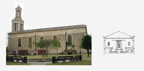
To a higher place is a photo of St Matthew'due south Church building at Brixton, UK. A lateral section drawing is to its right.
Photo source: geograph.org.uk Drawing source: british-history.ac.u.k.
Offset Section
A section is said to exist offset when the cutting airplane consists of multiple segments (as mentioned higher up under 'Cutting Planes').
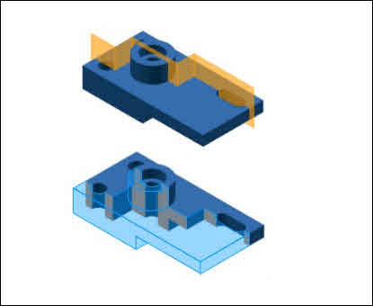
The concept of beginning section drawing
Source: MokhdarPadeli
Broken-out Section
In this case the cutting aeroplane is multi-segment and does not extend entirely across the particular. Instead information technology turns perpendicular to the view midway.
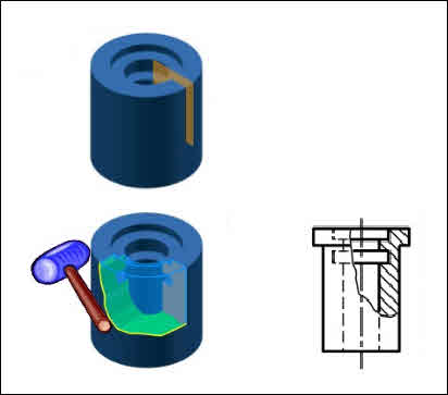
The concept of a broken-out department drawing
Source: MokhdarPadeli
Revolved Department
Here the section cartoon is rotated by 90 degrees from its actual position.
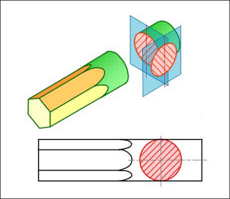
The concept of a revolved section drawing
Source: Beerza
Removed Section
A removed section cartoon is when the department view is not positioned as projected from another view of the object. Removed sections are typically used when there are space constraints in the layout space.
Almost often the removed section does not evidence details of what is behind the cutting plane.
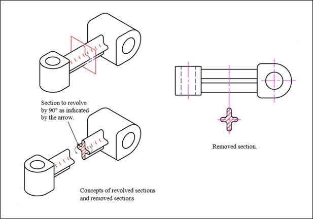
The concept behind a removed section drawing
Source: makingthat.wordpress.com
How to Create a Section Drawing
The all-time style to create a section drawing of an object is to utilise CAD (computer-aided pattern) software. There are several such software platforms bachelor with varying capabilities, and the more the capabilities the higher the prices, which range from $30 to more than than $10,000 (!!).
Determine where you lot want to piece (section) your object:
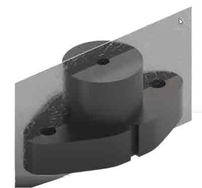
Using the cutting plane line tools of your CAD software, draw the cutting plane line (named AA in this case):
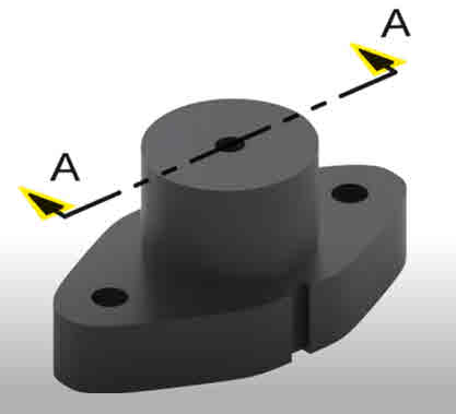
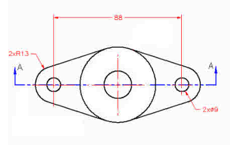
Y'all can draw the cutting plane line in a program view if yous demand to:
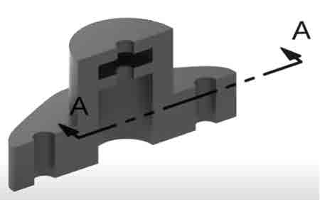
Click the 'create section' tool in your CAD software, and the object volition exist sectioned:
Convert the section to 2D view if you wish (using the tools in your CAD software).
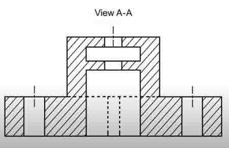
The diagonal lines in a section view are chosen 'hatching."
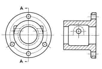
Should hidden lines be shown in a section view?
Hidden lines should not be shown in section views unless absolutely necessary, as in the example below:
How to Draw aSection Perspective
Also called a "perspective department", a section perspective is usually produced by architects to illustrate a lifelike sectional view of a project. Information technology typically tapers towards the rear (hence the name 'perspective'), merely every bit it would in real life.
The perspective is normally colored and shaded in the proposed colors and may include furniture and people:
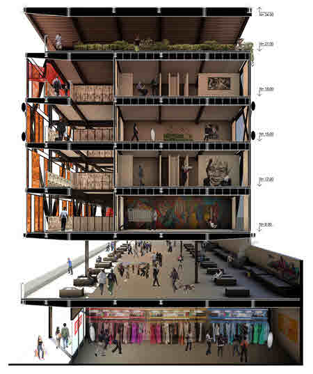
A Department Perspective Drawing Example
Source: Archdaily.com
The method is exactly similar to 'How to create a Section Drawing' explained above, with the exception of the final stride:
Using CAD software, create the object in 3D
Determine where you desire to section the building
Ready your cutting aeroplane line in plan view
Section the 3D building, add 3D people and furniture
Realistically color and shade ('render') the consequence using using your CAD software's rendering tool.
How Do You Read a Section Cartoon?
Section Line Naming
Since a single drawing may incorporate several section lines, there must exist a fashion of referring to each section line uniquely.
A unique letter of the alphabet is placed at either endof a cut plane line, and the cut airplane line is named later on the ii messages. For example, the cut plane lines in the following diagram are named 'AA', 'BB' and 'CC':
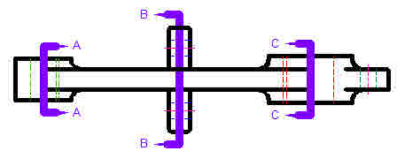
Source: SMHS Shop
In the instance of drawing sets containing many section drawings, the section drawings are frequently grouped together on a sheet separate from the parent drawing. In that example, the cutting aeroplane line lettering would besides comprise the name of the parent drawing sheet:
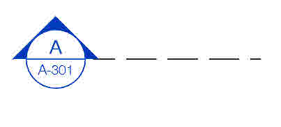
In the above diagram, the parent drawing of the department is sheet number A-301.
Understanding the Department View
The section line e'er ends in arrowheads. To sympathise how the section drawing is orientated in real infinite, imagine yous are standing on the side of the parent object opposite the side the arrowheads point to.
This is best explained past the beneath diagram:

Source: msbears.com
Any questions about the above diagram or other concepts in this article? If so, please driblet them in the comment box beneath or contact u.s.a. from the contact form at upper right.
Demand Professional person CAD Drafting?
As you may have guessed, CAD services are our specialty. Acquire more about them at https://themagnumgroup.net/ . It would be a pleasure to serve you.
Source: https://themagnumgroup.net/Blog/section-drawing/
0 Response to "How to Draw a Tunnel in Plan View"
Post a Comment